Objective: Use the LCD shield to control display and learn basic fabrication techniques to create a simple LCD display.
Please include the pre-lab responses, pictures of your fabricated LCD display and working LCD on the lab report. It is due on Wednesday, Oct 15th at 5 pm to Coursework's dropbox. No hard copy.
Pre-lab
Refer to the tutorials, schematics, board layouts, source code, and datasheets to answer the following questions.
Part 3a: Driving an LCD display
Part 3b: Fabricating an LCD display
Part 3a: Driving an LCD display
- a) Briefly explain how to drive a dot matrix LCD display using time multiplexing.
b) Draw the waveforms necessary to generate a checkerboard pattern on a 4x4 display. - a) Examine LCD_2010.pde. What does the program do?
b) How does the program address an individual pixel?
c) This program is designed to address a dot matrix display, but the commercial display provided with the kits is a 16-segment display. How could you modify the code to make it easier to use this display?
(Note: You will only be able to address 2 digits with the shield and include the modified code on lab report ) - d) Optional: Modify the code to display alphanumeric information.
- a) What function do the resistors serve?
b) How important is the value of the resistor? - a) Explain why LCDs use a biphasic waveform for driving.
b) What would happen if you used a single polarity to drive the LCD?
Part 3b: Fabricating an LCD display
- Briefly explain the basic operating principle of a liquid crystal display.
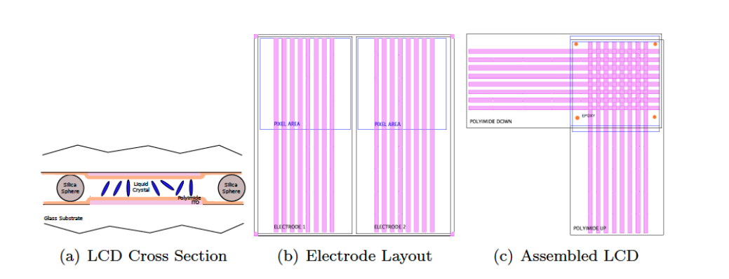
- The cross section of an LCD is shown below. Describe the purpose of each layer. What important layers are not shown?
Lab

|
Components used in the LCD lab
|
Assembly
|
Assembling the LCD Shield:

|


|
Fabricating an LCD display:
For the display to function properly, the samples need "micro" grooves on the electrodes and adequate spacing between the electrodes. The grooves will be created in polyamide and silica spheres will provide the spacing.
For the display to function properly, the samples need "micro" grooves on the electrodes and adequate spacing between the electrodes. The grooves will be created in polyamide and silica spheres will provide the spacing.
- Spin coat polyamide (3000 RPM, 45 sec)
- Bake (150 Celsius degree, 5 min)
- Create grooves along the electrodes with a microfiber
- Apply dilute solutions of 5 micrometer silica beads to pixel area of one electrode
- Contact the pixel areas of the two electrodes and spread silica solutions
- Separate the electrodes and remove excess solution
- Apply epoxy to one electrode
- Align and bond the electrodes
- Cure epoxy (5 min)
- Wick in liquid crystal
LCD Files:
|
|
| ||||||
|
|
| ||||||
