Objective: Use the LED mount and the LED drive shield to control an LED display using the Arduino.
Please include the pre-lab responses and pictures of your working OLED shield in the lab report. The report is due on Friday, October 21st at 7pm on Courseworks.
Pre-lab
Refer to the board layouts, tutorials, schematics, datasheets and source code provided to answer the following exercises.
- a) Compare and contrast the direct drive scheme and the MAX 7219 drive scheme.
b) What are the advantages and limitations of each drive scheme? - a) Examine led_direct_2012.ino and led_7219_2012.ino. What does each program do?
b) How does each program address an individual LED?
c) Modify these programs to display useful action. (For example: implement a binary clock or a scrolling text display. Be creative!) - List some advantages and disadvantages of OLED displays.
- The organic layers will be deposited using a thermal evaporator in a nitrogen glovebox. Why is it necessary to work in a nitrogen environment?
- a) Briefly describe the process of thermal evaporation.
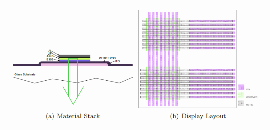
b) Why is it necessary to perform the evaporation under vacuum? - a) The OLED material layers are shown below. Briefly describe the function of each layer.
b) Draw the band diagram for the OLED.
Lab
|
Components Used in Assembling the LED matrix Adapter Board:
|
|
Components Used in Assembling the LED Drive Shield:
|
LED Matrix Adapter Board Assembly:
Read the LED matrix datasheet PDF. The pin configuration of the commercial LED matrices can be confusing. For example, if you want to turn on the pixel in the first row and first column, you have to use pin 9 and pin 13. Wouldn't it be easier if you could use the first pin on one side for row 1 and first pin on the other side for column 1? Now you can!
Your kit has an adapter board to change the pinouts. Here's how to assemble it:
Your kit has an adapter board to change the pinouts. Here's how to assemble it:
|
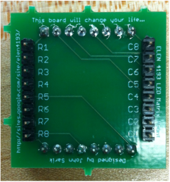
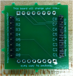
1. Place and solder the two 8 pin male headers into R1-R8 and C1-C8
|
|
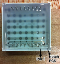
Note: Pin 1 is on the side of the LED with the notch labelled as PC5
|
|
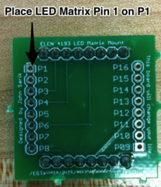
2. Find pin 1 on the LED matrix and align it with P1 on the board
|

|
3. Then solder the LED matrix into P1-P8 and P9-P16
Assembled LED matrix adapter board |
LED Drive Shield:
Note: Make sure the MAX7219 IC is oriented such that its notch matches the notch outline on the silkscreen
Note: Since the 10uF capacitor is polarized, remember to solder its cathode to the negative terminal on the board Now you have finished assembled the OLED Shield! Remember the orientation of the LED matrix is important. If your display does not work properly, then try to rotate the matrix 180 degrees. Test the programs on your OLED shield. |
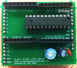
Remember to orient the IC's notch to the notch on the silkscreen
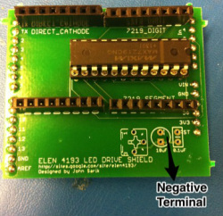
Align the 10uF capacitor's cathode into the negative terminal on the silkscreen
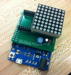
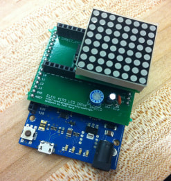
Final Assembled OLED Shield
|
OLED Display in Action:
Useful Links:
Arduino Libraries for MAX7219:
OLED Files:
|
|
|
| ||||||||
|
|
|
| ||||||||
|
|
|
| ||||||||
|
|
|
| ||||||||
|
|
| |||||||
